️Headphone Jack With Mic Wiring Diagram Free Download Gambr.co
What is a Switch? How to Read an Audio Jack Schematic Are Audio Jack Switches Needed? Switching Audio Between Speakers and Headphones Detect When the Plug Is Inserted Controlling Other Portions of a Circuit Independent of the Audio Signals Audio jacks have been around for decades and have been used in a wide variety of applications.

Electrical Creating a custom TRRS splitter for headphones and mic; how to handle the mic’s TRS
1 Without knowing what kinds of connections you are dealing with, it's not really possible to answer your question directly. There are a few different reasons you could have 3 conductors on the plug.
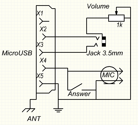
MicroUSB to 3.5 or 2.5 jack headset pinout diagram
Pinouts for both, starting from the tip, are as follows: Pin 2 is the clone RX/TX pin. Not used except in programming the Radio. Speaker/mic cable for the Yaesu VX-170, VX-6R, VX-7R, VX-120 and others. This cable has the unusual and hard-to-find threaded 3.5mm 4-conductor connector with o-ring.
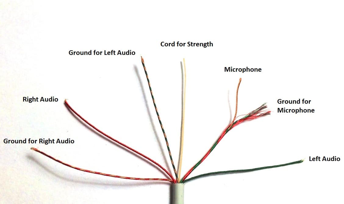
Wiring Microphone Jack
This 4-pole jack plug pinout is for modern Android and Apple smartphones that follow the modern standard. Newer equipment such as PC headsets, gaming headsets, and headphones for mobile phones usually follow this wiring scheme. You will also find it on the iPhone, iPad, Kindle Fire, Razer Blade, Macbook Pro, or the newer Ultrabooks.
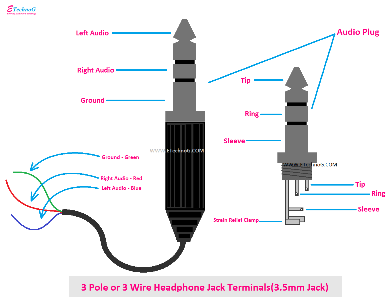
Headphone Jack Wiring, Connection, Terminals, PinOut, Color Codes ETechnoG
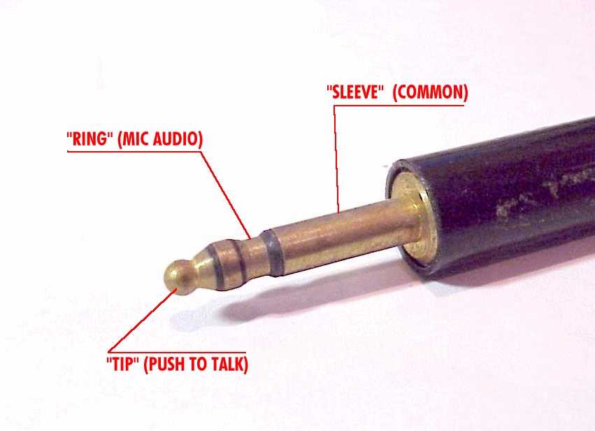
History: This form of microphone connector has been around since World War II. The basic design for this style of connector has roots in the design for a plug and jack set used with headsets. The headset plug diameter was only a two circuit plug (sleeve and tip) and 0.25" in diameter.

Headphone Jack Wiring, Connection, Terminals, PinOut, Color Codes ETechnoG
The intended application for a phone connector has also resulted in names such as audio jack, headphone jack, stereo plug, headphone jack, microphone jack, aux input, etc. Among audio engineers, the connector may often simply be called a quarter inch to distinguish it from XLR, another frequently-used audio connector. These naming variations.
4 Pole Wireless Mic Headphone Jack Mini Xlr Wiring Diagram
This type of connector could be used fine in audio for headphones that use a TRS jack - i.e. just headphones, and no microphone.. Standard 3.5 mm jack pinouts. Source: Prohardver.. for a four-pin version you might use the rectangle as a fourth pin. The four-pin plugs are known as TRRS (tip, ring, ring, sleeve) and the pins named as T, R1.

mic headphone jack wiring diagram
Show quoted text. From: Paul Godwin via groups.io. Sent: Friday, December 25, 2020 12:15 AM. To: [email protected]. Subject: Re: [YAESU-FTDX10] Mic connector. On Tue, Dec 22, 2020 at 06:43 AM, Dick wrote: ps: whatever was Yaesu thinking of when they went. from the sturdy 8 pin connector to these trash phone.

Wiring 3 Conductor Audio Jack
For example, Cobra 4 Pin radios are wired 1) Shield 2) Audio 3) Transmit 4) Receive while Midland 4 Pin radios are wired 1) Audio 2) Shield 3) Receive 4) Transmit. There are some radio brands that have the same general wiring (such as Cobra and Uniden) but that is not always the case. The list below offers some microphone wiring information.

Headphone Mic Wiring Diagram
Though the purpose is the same, the size, specific wiring, inclusion of a microphone, connection quality, and compatibility differ from jack to jack, plug to plug, and plug to jack.. The 6.35mm headphone jack/plug is found in many audio interfaces, headphone amplifiers, mixing consoles and recording devices. Size Adapters. Of the 4 sizes.

How To Wire A Microphone Jack
4 It seems many PC gaming wired analog headsets have two separate 3.5mm "TRS" (3-conductor Tip, Ring, Sleeve) phono plugs: One for stereo audio output from the PC to the headphones. One for microphone audio input from the mic to the PC. What is the typical pinout for the TRS mic plug?
AeroElectric Connection Aircraft Microphone Jack Wiring
Ask a question Comment Edit Submit New 3.5 mm, 2.5 mm or 6.25 mm is often used in various audio hardware, including computer audiocards A TRS connector (tip, ring, sleeve) also called an audio jack, phone jack, phone plug, jack plug, stereo plug, mini-jack, mini-stereo, or headphone jack, is a common analog audio connector.

Headphone Jack With Mic Wiring Diagram Easy Wiring
Pinouts. These are the TRRS jack breakout board pins. Sleeve - This is the microphone pin (the sleeve or S in TRR S ). Right - This is the right audio pin (the first ring or R in T R RS). RSw - This is the right switch pin. When the plug is not inserted, this pin is connected to the right contact. When the plug is inserted, this pin will float.

wiring audio jack
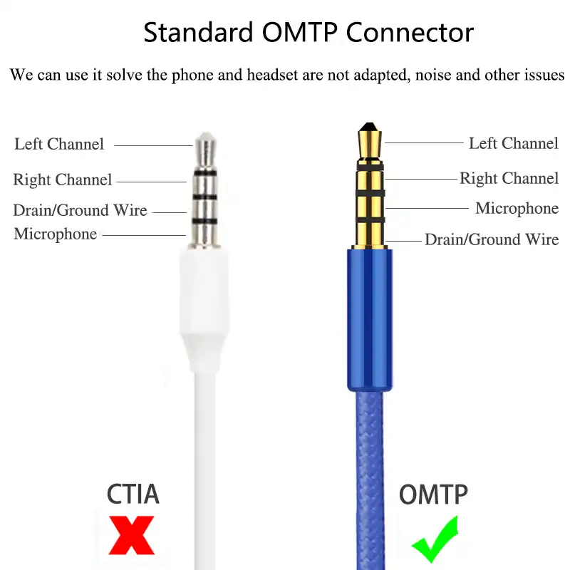
(From: Li Xuejun /123rf.com) The TRS-type plug can only be used for either microphone input or stereo audio input, and not both. This is why it's common for headphones that use this type of plug to come outfitted with two, sometimes colored pink and green, to distinguish between audio and microphone input.

microphone jack pinout advancefiber.in
1. TS Type Male Audio jack These types of audio jacks does not support stereo sound and microphone, which means there is no left and right. You will get same sound from both the sides. Below is the pinout of TS type male audio jack. Application: Still used on musical equipment (especially in electric guitars) and aviation radios. 2.
Headphone Microphone Jack Wiring Diagram
The "jack" is the "female connector," while the "plug" is the "male connector." The term "jack" actually originates from the " jack-knife switch ." This was used on early telephone switchboards and patented by C.E. Scribner in 1874. Unfortunately, the audio industry has yet to unite on the distinctions between plugs and jacks.